

Hook it up, make it shine!
Next I take out a ‘breadboard’ to start plugging in all my little LED light bulbs in a row. Each bulb needs power with + on a pin & – on another. They each have data pins for ‘in’ and ‘out’ to tell them what to do. These are called Neopixels and are fairly popular. (This is how you can buy these any-color LED strips now, and have them do tons of cool patterns.)
I decided to run CircuitPython on this board, and reserve the right to change my mind. I like the python-based options, because instead of needing a special program to ‘compile’ your code and ‘flash’ it to your device, it shows up as a USB drive on any PC. Simply drag & drop your libraries, or edit your code. The moment you do, the board sees the file has been modified and ‘interprets’ the new file immediately. That also means you could drag & drop your coder-buddies neat program without any coding skills of your own!

I ran out of little wires to hook things together, but my colleague told me of a neat trick. Use the strands of Cat6 wire, as they’re the right thickness and can be cut to any length! With a google search and some copy/paste I had those LEDs making multiple different displays of color. In a couple sessions, I had compiled 6 different ‘modes.’ I’ll likely save the best to be ‘unlocked’ by solving some sort of riddle.
I got them to do stuff, but they weren’t behaving very well. Some would flicker, be dim, or not the right color. They didn’t get worse further from the power source, so it wasn’t a bad connection. I knew capacitors help to filter and provide a ‘cushion’ of energy, so I decided to put one in. With some research, I learned about “de-coupling” your circuit from the board through a series of different-sized capacitors at different locations. This keeps ambient spikes from reaching your main controller board. I spaced 3 capacitors throughout the LED circuit, with values varying by degrees of 10. That, along with a standard resistor made it behave perfectly!
My buttons wouldn’t fit my breadboard, so I skipped testing them. Instead, I focused on the I2C serial connection. The Grove connection was rather specific, so I added other breakouts for StemmaQT/Qwiic & ‘Breakout Garden’ which are standards that others use. That way, folks weren’t locked into a single vendor. I got my board to recognize and list devices on the I2C bus, so I knew it was hooked up correctly.
At this point, my mushrooms were over due for their “6-12 day” delivery period, so I checked in. Turns out that’s the domestic side and it could actually take a whole 30 days to arrive! If I wanted a prototype in-hand to test and send to the conference in May, I can’t wait until the end of April.

With a leap of faith, I went ahead and uploaded my badge design. PCBway does an initial review process, to be sure they can carry-out the order. Cost was negligible, so I ordered 10 instead of the initial 5-piece minimum. At less than $6 each, they made and shipped my board in about 2 days! I paid for better shipping, and it arrived within a week, mere days after the mushrooms!

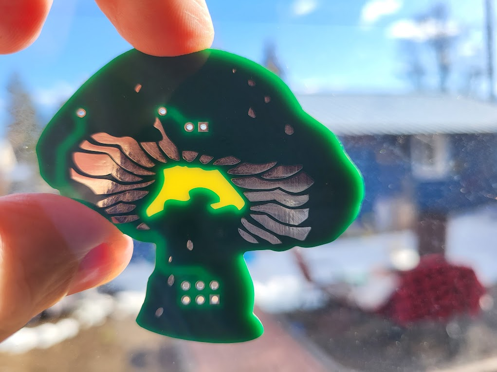
I used a different finish on the mushrooms, which had a tin/silver finish. On the badge, I wanted to keep the copper look. The mushroom is meant to have the parts mounted on the back, with the light glowing through the center. I experimented with a couple colors, but found yellow to be the best match with the board.
Now it’s just after Easter, and I have a couple weeks to test, assemble, and tweak my badge before the conference in May! The next installment will include the badge prototype.

Pingback: Building the Blinky – Part 2 | Josh 'n' More